

Arduino Quick Start
2. Devices & Examples
3. M5Unified
4. M5GFX
5. Extensions
Unit
Module
Atomic
Tab5
IoT
Accessories
CoreMatrix M5PM1 & M5IOE1 Power Management
1. Multi-Level Power Switching Design
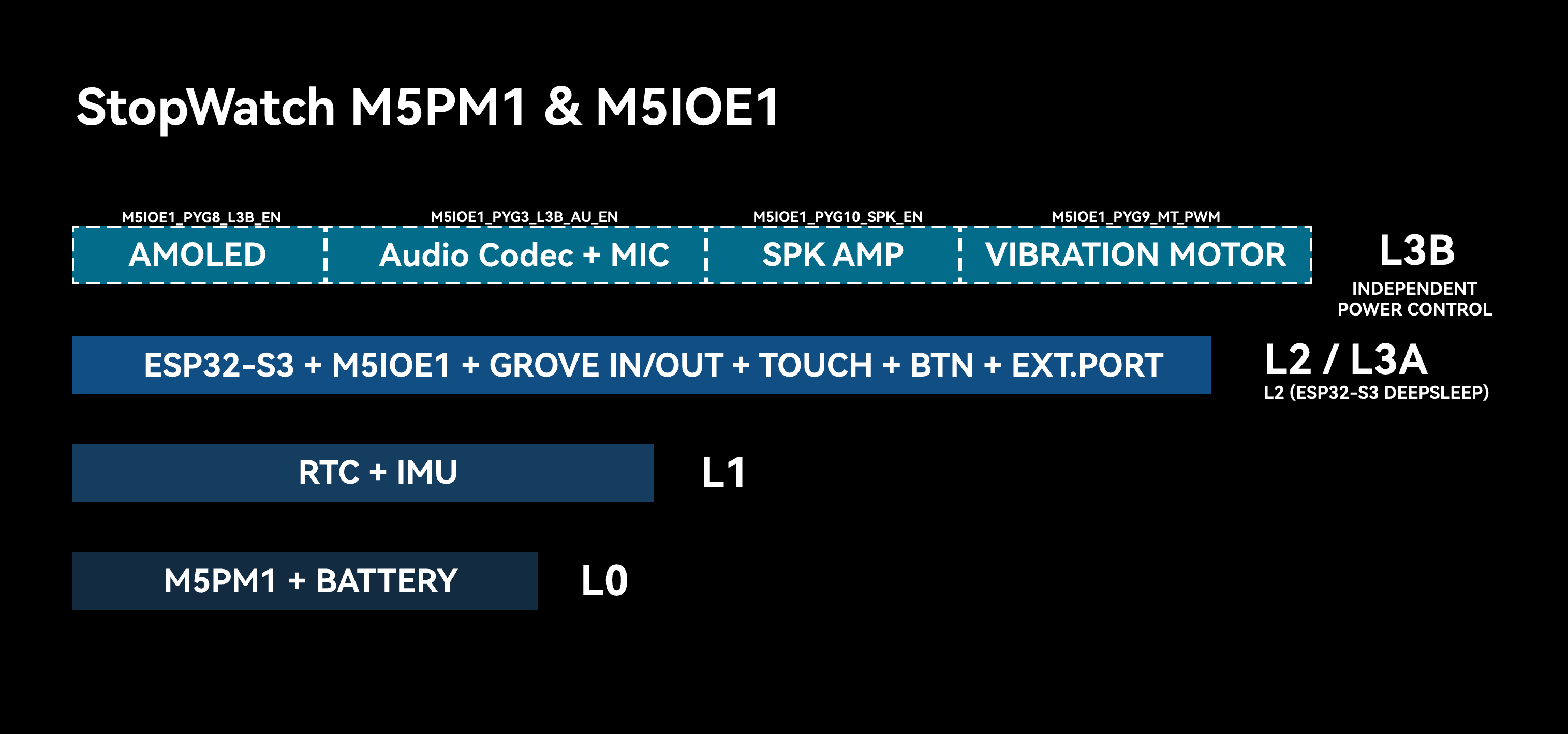
CoreMatrix integrates the Stamp Timer Power2 (M5PM1) and M5IOE1 with hardware circuits to implement multi-level power switching. Each level corresponds to a different controller operating state and power state for peripherals and interfaces. You can switch the controller state and related power enables as needed, turning off unused peripherals to reduce overall power consumption.
M5PM1 / M5IOE1 Driver Libraries
The M5PM1 / M5IOE1 driver libraries make it easy to configure their pin functions for low-power wakeup and peripheral power control.
L0
At this power level, the battery keeps M5PM1 powered. This level remains powered as long as the battery is not depleted, and M5PM1 supports basic power on/off operation via buttons.
L1
At this power level, power is enabled for the IMU, the KEY1~KEY3 button pull-ups, and related logic. This level uses the M5PM1 3V3_L1 output, which can be controlled with the following APIs.
pm1.setLdoEnable(true); // L1 ON
pm1.setLdoEnable(false); // L1 OFFIn addition, BMI270 INT1 is connected to M5PM1 G4, and KEY1~KEY3 are connected to M5PM1 G0~G2 respectively. To wake M5PM1 from the IMU or a button, keep L1 powered and then put M5PM1 into sleep:
pm1.setLdoEnable(true);
pm1.ldoSetPowerHold(true);
pm1.setLedEnLevel(true);
pm1.shutdown();L3A
At this power level, power is enabled for ESP32-C61, M5IOE1, the system I2C bus, and controller-related peripherals. This level uses the M5PM1 DC-DC output 3V3_L3A, which can be controlled with the following APIs.
pm1.setDcdcEnable(true); // L3A ON
pm1.setDcdcEnable(false); // L3A OFFL3B
Level L3B controls power or related settings for peripherals such as the LED matrix, microSD, buzzer, and Grove. Control is implemented through the M5IOE1 I/O expander, allowing some peripherals at this level to be controlled independently.
| M5IOE1 | PYG1 | PYG2 | PYG3 | PYG4 | PYG5 | PYG8 | PYG10 | PYG11 |
|---|---|---|---|---|---|---|---|---|
| microSD | PYB_TF_EN | PYB_TFCARD_DET | ||||||
| Buzzer | PYB_BUZZER_EN | PYB_BUZZER_PWM | ||||||
| Charge | PYB_CHG_PROG | PYB_CHG_STAT | ||||||
| LED Matrix | PYB_LEDS_EN | |||||||
| Grove 5V | PYB_GROVE_EN |
- PYB_TF_EN: microSD
TF_3V3_L3Bpower enable - PYB_BUZZER_EN: buzzer
BUZZER_3V3_L3Bpower enable - PYB_CHG_PROG: charge-current setting control
- PYB_LEDS_EN: LED matrix
LEDS_3V3_L3Bpower enable - PYB_GROVE_EN: Grove 5V output enable
- PYB_CHG_STAT: charge-status input; low indicates charging
- PYB_TFCARD_DET: microSD detection; low indicates a card is detected
- PYB_BUZZER_PWM: buzzer PWM drive, channel
M5IOE1_PWM_CH3(index 2)
Peripheral power can be controlled independently with the M5IOE1 APIs below:
ioe1.pinMode(M5IOE1_PIN_4, OUTPUT);
ioe1.digitalWrite(M5IOE1_PIN_4, HIGH);The 5V output of the Grove interface is controlled by PYB_GROVE_EN (PYG5). The M5Unified cfg.output_power option defaults to true, so Grove 5V is already enabled after M5.begin(). It can be controlled with the following APIs:
M5.Power.setExtOutput(true); // 打开 Grove 5V
M5.Power.setExtOutput(false); // 关闭 Grove 5V2. M5PM1 Sleep
Manual Sleep
M5PM1 can be put into sleep mode by the program to reduce overall power consumption. By default, setting sleep directly falls back to the low-power supply state, where only M5PM1 remains powered.
pm1.shutdown();To keep L1 circuits such as the IMU and button pull-ups powered, use the M5PM1 driver library to configure L1 power retention and the corresponding wakeup source, then call pm1.shutdown().
I2C Idle Sleep
M5PM1 can be configured to enter sleep automatically when I2C is idle. After it enters sleep, the first communication from the ESP32 is used to wake M5PM1, and the effective communication completes on the next transaction.
m5pm1_err_t setI2cSleepTime(uint8_t seconds);3. M5PM1 Timer
M5PM1 supports a timer that performs operations such as power-on, power-off, or reset when the countdown ends.
m5pm1_err_t timerSet(uint32_t seconds, m5pm1_tim_action_t action);typedef enum {
M5PM1_TIM_ACTION_STOP = 0b000, // 停止,无动作
// Stop, no action
M5PM1_TIM_ACTION_FLAG = 0b001, // 仅设置标志
// Set flag only
M5PM1_TIM_ACTION_REBOOT = 0b010, // 系统复位
// System reboot
M5PM1_TIM_ACTION_POWERON = 0b011, // 开机
// Power on
M5PM1_TIM_ACTION_POWEROFF = 0b100 // 关机
// Power off
} m5pm1_tim_action_t;Timed Power-On / Power-Off Example
Example: Press KEY1 to set an automatic power-on after 3 seconds followed by an immediate power-off, or press KEY2 to set an automatic power-off after 5 seconds. After power-off, click PWR_BTN to power the device on again.
#include <M5Unified.h>
#include <M5PM1.h>
M5PM1 pm1;
static void drawState(uint8_t state)
{
M5.Display.startWrite();
M5.Display.fillScreen(TFT_BLACK);
M5.Display.drawRect(0, 0, 16, 16, TFT_WHITE);
if (state == 0) {
M5.Display.fillRect(7, 7, 2, 2, TFT_WHITE);
} else if (state == 1) {
M5.Display.fillRect(3, 3, 4, 4, TFT_WHITE);
} else {
M5.Display.fillRect(9, 9, 4, 4, TFT_WHITE);
}
M5.Display.endWrite();
M5.Display.display();
}
void setup()
{
auto cfg = M5.config();
cfg.serial_baudrate = 115200;
M5.begin(cfg);
M5.Display.setColorDepth(8);
M5.Display.setRotation(1);
M5.Display.setBrightness(128);
const m5pm1_err_t err = pm1.begin(&M5.In_I2C, M5PM1_DEFAULT_ADDR, M5PM1_I2C_FREQ_100K);
if (err != M5PM1_OK) {
Serial.printf("M5PM1 init failed: %d\n", err);
while (true) delay(1000);
}
Serial.println("KEY1: power on after 3s");
Serial.println("KEY2: power off after 5s");
drawState(0);
}
void loop()
{
M5.update();
if (M5.BtnA.wasClicked()) {
Serial.println("Set power-on timer: 3s");
drawState(1);
delay(200);
pm1.timerSet(3, M5PM1_TIM_ACTION_POWERON);
pm1.shutdown();
}
if (M5.BtnB.wasClicked()) {
Serial.println("Set power-off timer: 5s");
drawState(2);
pm1.timerSet(5, M5PM1_TIM_ACTION_POWEROFF);
}
delay(20);
}4. IMU Wakeup
BMI270 Driver Library
IMU Wakeup of M5PM1
When power switches to L1 mode, the CoreMatrix IMU, KEY1~KEY3 button pull-ups, and M5PM1 remain powered. After IMU wakeup is configured, M5PM1 enters sleep while retaining the L1 output power (3V3_L1_EN) required for the BMI270 to operate.
You can then flip or move the device to make BMI270 INT1 output low, which wakes M5PM1 and restarts the system.
After M5PM1 wakes, it runs the L0, L1, and L3A power-up sequence again, and ESP32-C61 repeats initialization.
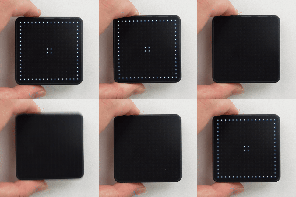
Example: After startup, click button A (KEY1) to configure IMU interrupt mode and M5PM1 L1 power retention; M5PM1 then enters sleep. Flip or move the device to trigger an M5PM1 wakeup, and ESP32-C61 powers up again.
#include <M5Unified.h>
#include <M5PM1.h>
#include <Wire.h>
#include "SparkFun_BMI270_Arduino_Library.h"
BMI270 imu;
M5PM1 pm1;
void setup(void)
{
M5.begin();
Serial.begin(115200);
Wire.setPins(M5.getPin(m5::pin_name_t::in_i2c_sda), M5.getPin(m5::pin_name_t::in_i2c_scl));
// Initialize PM1
m5pm1_err_t err = pm1.begin(&M5.In_I2C, M5PM1_DEFAULT_ADDR, M5PM1_I2C_FREQ_100K);
if (err == M5PM1_OK) {
Serial.println("PM1 initialization successful");
pm1.gpioSetWakeEnable(M5PM1_GPIO_NUM_4, true);
pm1.gpioSetWakeEdge(M5PM1_GPIO_NUM_4, M5PM1_GPIO_WAKE_FALLING); // Falling edge
} else {
Serial.printf("PM1 initialization failed, error code: %d\n", err);
}
// Check if sensor is connected and initialize
// Address defaults to 0x68
while(imu.beginI2C(BMI2_I2C_PRIM_ADDR, Wire) != BMI2_OK)
{
Serial.println("Error: BMI270 not connected, check wiring and I2C address!");
delay(1000);
}
imu.disableFeature(BMI2_ANY_MOTION);
Serial.println("BMI270 initialization successful");
M5.Display.setColorDepth(8);
M5.Display.setRotation(1);
M5.Display.setBrightness(128);
M5.Display.fillScreen(TFT_BLACK);
M5.Display.drawRect(0, 0, 16, 16, TFT_WHITE);
M5.Display.fillRect(7, 7, 2, 2, TFT_WHITE);
M5.Display.display();
}
void loop(void)
{
M5.update();
if (M5.BtnA.wasPressed()) {
int8_t ret = imu.enableFeature(BMI2_ANY_MOTION);
// Optional
// bmi2_sens_config config;
// config.type = BMI2_ANY_MOTION;
// config.cfg.any_motion.threshold = 0xA0; // 1LSB equals to 0.48mg. Default is 83mg. Lower is more sensitive
// config.cfg.any_motion.duration = 0x0A; // 1LSB equals 20ms. Default is 100ms.
// ret |= imu.setConfig(config);
//
bmi2_int_pin_config intPinConfig;
intPinConfig.pin_type = BMI2_INT1;
intPinConfig.int_latch = BMI2_INT_NON_LATCH;
intPinConfig.pin_cfg[0].lvl = BMI2_INT_ACTIVE_LOW;
intPinConfig.pin_cfg[0].od = BMI2_INT_PUSH_PULL;
intPinConfig.pin_cfg[0].output_en = BMI2_INT_OUTPUT_ENABLE;
intPinConfig.pin_cfg[0].input_en = BMI2_INT_INPUT_DISABLE;
ret |= imu.setInterruptPinConfig(intPinConfig);
ret |= imu.mapInterruptToPin(BMI2_ANY_MOTION_INT, BMI2_INT1);
if (!ret) {
Serial.println("BMI270 AnyMotionInterrupt enabled successfully");
} else {
Serial.println("Failed to enable BMI270 AnyMotionInterrupt");
}
M5.Display.fillScreen(TFT_BLACK);
M5.Display.drawRect(0, 0, 16, 16, TFT_WHITE);
M5.Display.fillRect(5, 5, 6, 6, TFT_WHITE);
M5.Display.display();
delay(1000);
// Shutdown
pm1.setLdoEnable(true);
pm1.ldoSetPowerHold(true);
pm1.setLedEnLevel(true);
pm1.shutdown();
}
}Example effect demonstration:
IMU Wakeup of ESP32-C61
The M5PM1 G3 IRQ pin is connected to ESP32-C61 G2 on the board, so ESP32-C61 can be woken through a chained wakeup signal. The steps are as follows:
- Configure M5PM1 G4 as an input. This pin is connected to the BMI270 INT1 output signal.
- Configure M5PM1 G3 as the IRQ output signal pin. When the state of G4 (the BMI270 interrupt signal) changes, G3 IRQ outputs an interrupt signal.
- Configure ESP32-C61 G2 as a falling-edge interrupt input to detect the M5PM1 G3 IRQ. The actual deep-sleep code is left commented out in the example.
- Flip or move the device: the BMI270 wakeup signal triggers M5PM1 G3 IRQ, which triggers the ESP32-C61 G2 interrupt handler, and the CoreMatrix matrix pattern changes accordingly.
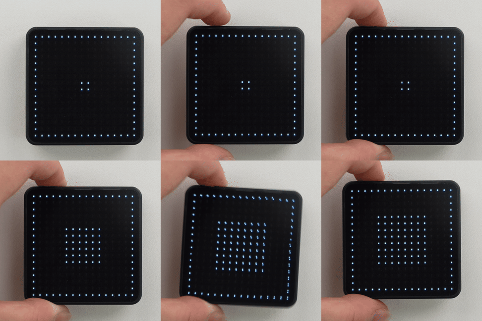
Example: After startup, click button A (KEY1) to configure IMU interrupt mode and register the ESP32-C61 G2 falling-edge interrupt. Flip or move the device to trigger the GPIO interrupt handler, and the matrix pattern changes from the waiting state to the triggered state. Click button A again to clear the M5PM1 IRQ flags and repeat the test. If you enable the commented-out deep-sleep code, motion wakes ESP32-C61, which then runs from setup() again.
#include <M5Unified.h>
#include <M5PM1.h>
#include <Wire.h>
#include "SparkFun_BMI270_Arduino_Library.h"
#include "driver/rtc_io.h"

BMI270 imu;
M5PM1 pm1;

void setup(void)
{
    M5.begin();
    Serial.begin(115200);

    Wire.setPins(M5.getPin(m5::pin_name_t::in_i2c_sda), M5.getPin(m5::pin_name_t::in_i2c_scl));

    // Initialize PM1
    m5pm1_err_t err = pm1.begin(&M5.In_I2C, M5PM1_DEFAULT_ADDR, M5PM1_I2C_FREQ_100K);

    if (err == M5PM1_OK) {
        Serial.println("PM1 initialization successful");
        pm1.irqClearGpioAll();
        pm1.irqClearSysAll();
        pm1.irqClearBtnAll();

        pm1.irqSetGpioMaskAll(M5PM1_IRQ_MASK_ENABLE);
        pm1.irqSetSysMaskAll(M5PM1_IRQ_MASK_ENABLE);
        pm1.irqSetBtnMaskAll(M5PM1_IRQ_MASK_ENABLE);

        pm1.irqSetGpioMask(M5PM1_IRQ_GPIO4, M5PM1_IRQ_MASK_DISABLE);
        pm1.gpioSetMode(M5PM1_GPIO_NUM_4, M5PM1_GPIO_MODE_INPUT);
        pm1.gpioSetPull(M5PM1_GPIO_NUM_4, M5PM1_GPIO_PULL_UP);

        pm1.gpioSetMode(M5PM1_GPIO_NUM_3, M5PM1_GPIO_MODE_OUTPUT);
        pm1.gpioSetDrive(M5PM1_GPIO_NUM_3, M5PM1_GPIO_DRIVE_PUSHPULL);
        pm1.gpioSetPull(M5PM1_GPIO_NUM_3, M5PM1_GPIO_PULL_UP);
        pm1.gpioSetOutput(M5PM1_GPIO_NUM_3, true);
        pm1.gpioSetFunc(M5PM1_GPIO_NUM_3, M5PM1_GPIO_FUNC_IRQ);
    } else {
        Serial.printf("PM1 initialization failed, error code: %d\n", err);
    }

    // Check if sensor is connected and initialize
    // Address defaults to 0x68
    while(imu.beginI2C(BMI2_I2C_PRIM_ADDR, Wire) != BMI2_OK)
    {
        Serial.println("Error: BMI270 not connected, check wiring and I2C address!");
        delay(1000);
    }
    imu.disableFeature(BMI2_ANY_MOTION);
    Serial.println("BMI270 initialization successful");

    M5.Display.setColorDepth(8);
    M5.Display.setRotation(1);
    M5.Display.setBrightness(128);
    M5.Display.fillScreen(TFT_BLACK);
    M5.Display.drawRect(0, 0, 16, 16, TFT_WHITE);
    M5.Display.fillRect(7, 7, 2, 2, TFT_WHITE);
    M5.Display.display();
}

volatile bool pm1IrqTriggered = false;

void ARDUINO_ISR_ATTR pm1_irq_handler()
{
    pm1IrqTriggered = true;
}

void loop(void)
{
    M5.update();

    if (pm1IrqTriggered) {
        pm1IrqTriggered = false;

        uint16_t status = 0;
        imu.getInterruptStatus(&status);
        Serial.printf("BMI270 interrupt status: 0x%04X\n", status);

        M5.Display.fillScreen(TFT_BLACK);
        M5.Display.drawRect(0, 0, 16, 16, TFT_WHITE);
        M5.Display.fillRect(4, 4, 8, 8, TFT_WHITE);
        M5.Display.display();
    }

    if (M5.BtnA.wasPressed()) {
        pm1.irqClearGpioAll();
        pm1.irqClearSysAll();
        pm1.irqClearBtnAll();
        int8_t ret = imu.enableFeature(BMI2_ANY_MOTION);
        // Optional
        // bmi2_sens_config config;
        // config.type = BMI2_ANY_MOTION;
        // ret |= imu.getConfig(&config);
        // config.cfg.any_motion.threshold = 0xE0;  // 1LSB equals to 0.48mg. Default is 83mg. Lower is more sensitive
        // config.cfg.any_motion.duration = 0x0A;   // 1LSB equals 20ms. Default is 100ms.
        // ret |= imu.setConfig(config);

        bmi2_int_pin_config intPinConfig;
        intPinConfig.pin_type = BMI2_INT1;
        intPinConfig.int_latch = BMI2_INT_NON_LATCH;
        intPinConfig.pin_cfg[0].lvl = BMI2_INT_ACTIVE_LOW;  // Active low
        intPinConfig.pin_cfg[0].od = BMI2_INT_PUSH_PULL;
        intPinConfig.pin_cfg[0].output_en = BMI2_INT_OUTPUT_ENABLE;
        intPinConfig.pin_cfg[0].input_en = BMI2_INT_INPUT_DISABLE;
        ret |= imu.setInterruptPinConfig(intPinConfig);
        ret |= imu.mapInterruptToPin(BMI2_ANY_MOTION_INT, BMI2_INT1);
        if (!ret) {
            Serial.println("BMI270 AnyMotionInterrupt enabled successfully");
        } else {
            Serial.println("Failed to enable BMI270 AnyMotionInterrupt");
        }

        M5.Display.fillScreen(TFT_BLACK);
        M5.Display.drawRect(0, 0, 16, 16, TFT_WHITE);
        M5.Display.fillRect(5, 5, 6, 6, TFT_WHITE);
        M5.Display.display();

        // Choose either of the two pieces of code below.
        pinMode(GPIO_NUM_2, INPUT_PULLUP);
        attachInterrupt(GPIO_NUM_2, pm1_irq_handler, FALLING);

        // esp_sleep_enable_ext1_wakeup(1ULL << GPIO_NUM_2, ESP_EXT1_WAKEUP_ANY_LOW);
        // rtc_gpio_pullup_en(GPIO_NUM_2);
        // Serial.println("Going to sleep now");
        // esp_deep_sleep_start();
    }
}Example effect demonstration:
5. KEY Wakeup
KEY Wakeup of M5PM1
When power switches to L1 mode, the CoreMatrix KEY1~KEY3 button pull-ups and M5PM1 remain powered. After KEY3 wakeup is configured, M5PM1 enters sleep while retaining the L1 output power (3V3_L1_EN) required for the button pull-ups and wakeup logic.
Pressing KEY3 then triggers a falling-edge wakeup signal on M5PM1 G2, waking M5PM1 and restarting it.
After M5PM1 wakes, it runs the L0, L1, and L3A power-up sequence again, and ESP32-C61 repeats initialization.
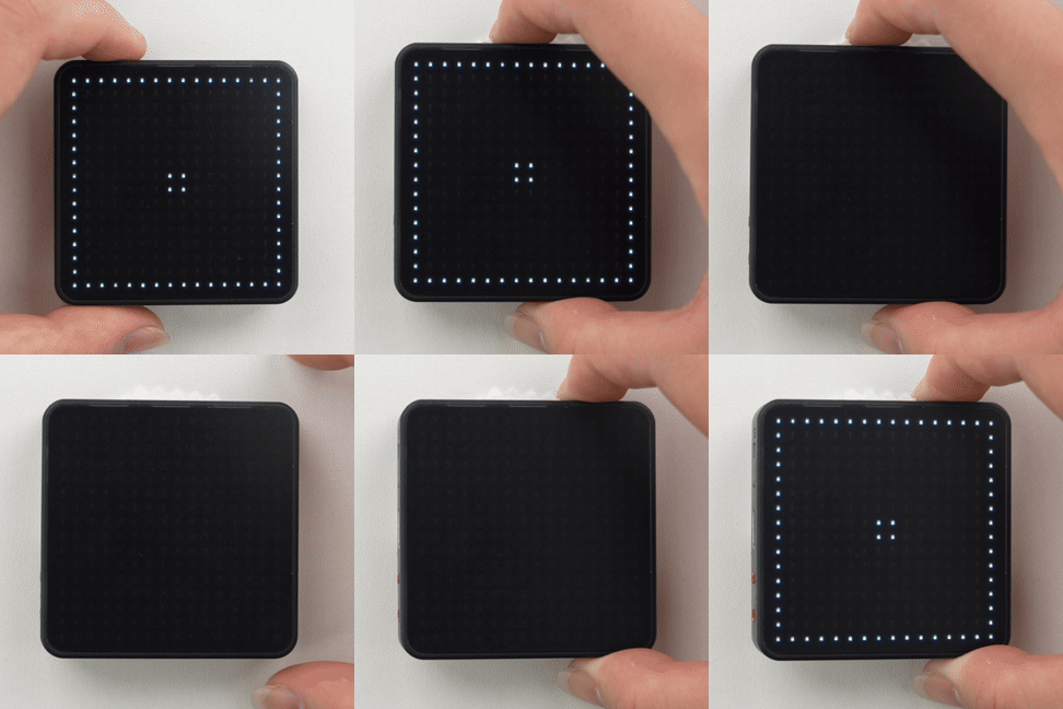
Example: After startup, click button B (KEY2) to configure KEY3 wakeup and M5PM1 L1 power retention; M5PM1 then enters sleep. Press KEY3 to trigger an M5PM1 wakeup, and ESP32-C61 powers up again.
#include <M5PM1.h>
#include <M5Unified.h>

M5PM1 pm1;

void setup(void)
{
    M5.begin();
    Serial.begin(115200);

    if (pm1.begin(&M5.In_I2C, M5PM1_DEFAULT_ADDR, M5PM1_I2C_FREQ_100K) != M5PM1_OK) {
        Serial.println("PM1 initialization failed");
        while (true) {
            delay(1000);
        }
    }

    Serial.println("PM1 initialization successful");
    M5.Display.setColorDepth(8);
    M5.Display.setRotation(1);
    M5.Display.setBrightness(128);
    M5.Display.fillScreen(TFT_BLACK);
    M5.Display.drawRect(0, 0, 16, 16, TFT_WHITE);
    M5.Display.fillRect(7, 7, 2, 2, TFT_WHITE);
    M5.Display.display();

    pm1.gpioSetWakeEdge(M5PM1_GPIO_NUM_2, M5PM1_GPIO_WAKE_FALLING);
    pm1.gpioSetWakeEnable(M5PM1_GPIO_NUM_2, true);
    pm1.setLdoEnable(true);
    pm1.ldoSetPowerHold(true);
}

void loop(void)
{
    M5.update();
    if (M5.BtnB.wasPressed()) {
        M5.Display.fillScreen(TFT_BLACK);
        M5.Display.drawRect(0, 0, 16, 16, TFT_WHITE);
        M5.Display.fillRect(5, 5, 6, 6, TFT_WHITE);
        M5.Display.display();
        Serial.println("KEY3 wakeup enabled");
        delay(1000);
        // Shutdown
        pm1.setLedEnLevel(true);
        pm1.shutdown();
    }
}Example effect demonstration:
KEY Wakeup of ESP32-C61
The M5PM1 G3 IRQ pin is connected to ESP32-C61 G2 on the board, so ESP32-C61 can be woken through a chained wakeup signal. The steps are as follows:
- Configure M5PM1 G2 as an input. This pin is connected to the KEY3 button.
- Configure M5PM1 G3 as the IRQ output signal pin. When the state of G2 (KEY3 pressed) changes, G3 IRQ outputs an interrupt signal.
- Configure ESP32-C61 G2 as a falling-edge interrupt input to detect the M5PM1 G3 IRQ. The actual deep-sleep code is left commented out in the example.
- Press KEY3: the button wakeup signal triggers M5PM1 G3 IRQ, which triggers the ESP32-C61 G2 interrupt handler, and the CoreMatrix matrix pattern changes accordingly.
Example: After startup, click button B (KEY2) to configure the M5PM1 G2 interrupt for KEY3 and register the ESP32-C61 G2 falling-edge interrupt. Press KEY3 to trigger the GPIO interrupt handler, and the matrix pattern changes from the waiting state to the triggered state. Click button B again to clear the M5PM1 IRQ flags and repeat the test. If you enable the commented-out deep-sleep code, pressing KEY3 wakes ESP32-C61, which then runs from setup() again.
#include <M5Unified.h>
#include <M5PM1.h>
#include "driver/rtc_io.h"

M5PM1 pm1;

void setup(void)
{
    M5.begin();
    Serial.begin(115200);

    // Initialize PM1
    m5pm1_err_t err = pm1.begin(&M5.In_I2C, M5PM1_DEFAULT_ADDR, M5PM1_I2C_FREQ_100K);

    if (err == M5PM1_OK) {
        Serial.println("PM1 initialization successful");
        pm1.irqClearGpioAll();
        pm1.irqClearSysAll();
        pm1.irqClearBtnAll();

        pm1.irqSetGpioMaskAll(M5PM1_IRQ_MASK_ENABLE);
        pm1.irqSetSysMaskAll(M5PM1_IRQ_MASK_ENABLE);
        pm1.irqSetBtnMaskAll(M5PM1_IRQ_MASK_ENABLE);

        pm1.irqSetGpioMask(M5PM1_IRQ_GPIO2, M5PM1_IRQ_MASK_DISABLE);
        pm1.gpioSetMode(M5PM1_GPIO_NUM_2, M5PM1_GPIO_MODE_INPUT);
        pm1.gpioSetPull(M5PM1_GPIO_NUM_2, M5PM1_GPIO_PULL_UP);

        pm1.gpioSetMode(M5PM1_GPIO_NUM_3, M5PM1_GPIO_MODE_OUTPUT);
        pm1.gpioSetDrive(M5PM1_GPIO_NUM_3, M5PM1_GPIO_DRIVE_PUSHPULL);
        pm1.gpioSetPull(M5PM1_GPIO_NUM_3, M5PM1_GPIO_PULL_UP);
        pm1.gpioSetOutput(M5PM1_GPIO_NUM_3, true);
        pm1.gpioSetFunc(M5PM1_GPIO_NUM_3, M5PM1_GPIO_FUNC_IRQ);
    } else {
        Serial.printf("PM1 initialization failed, error code: %d\n", err);
    }

    M5.Display.setColorDepth(8);
    M5.Display.setRotation(1);
    M5.Display.setBrightness(128);
    M5.Display.fillScreen(TFT_BLACK);
    M5.Display.drawRect(0, 0, 16, 16, TFT_WHITE);
    M5.Display.fillRect(7, 7, 2, 2, TFT_WHITE);
    M5.Display.display();
}

volatile bool pm1IrqTriggered = false;

void ARDUINO_ISR_ATTR pm1_irq_handler()
{
    pm1IrqTriggered = true;
}

void loop(void)
{
    M5.update();

    if (pm1IrqTriggered) {
        pm1IrqTriggered = false;
        Serial.println("PM1 IRQ triggered");

        M5.Display.fillScreen(TFT_BLACK);
        M5.Display.drawRect(0, 0, 16, 16, TFT_WHITE);
        M5.Display.fillRect(4, 4, 8, 8, TFT_WHITE);
        M5.Display.display();
    }

    if (M5.BtnB.wasPressed()) {
        pm1.irqClearGpioAll();
        pm1.irqClearSysAll();
        pm1.irqClearBtnAll();
        Serial.println("KEY3 IRQ enabled successfully");

        M5.Display.fillScreen(TFT_BLACK);
        M5.Display.drawRect(0, 0, 16, 16, TFT_WHITE);
        M5.Display.fillRect(5, 5, 6, 6, TFT_WHITE);
        M5.Display.display();

        // Choose either of the two pieces of code below.
        pinMode(GPIO_NUM_2, INPUT_PULLUP);
        attachInterrupt(GPIO_NUM_2, pm1_irq_handler, FALLING);

        // esp_sleep_enable_ext1_wakeup(1ULL << GPIO_NUM_2, ESP_EXT1_WAKEUP_ANY_LOW);
        // rtc_gpio_pullup_en(GPIO_NUM_2);
        // Serial.println("Going to sleep now");
        // esp_deep_sleep_start();
    }
}Example effect demonstration:
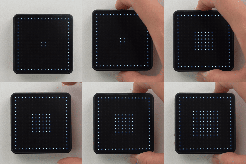
6. M5IOE1 Peripheral Control
CoreMatrix's M5IOE1 handles power enabling and status reading for L3B peripherals. The M5IOE1 APIs let you independently control the LED matrix, microSD, buzzer, and Grove 5V, and read the charge and card-insertion states.
| M5IOE1 Pin | CoreMatrix Function |
|---|---|
PYG1 | microSD power enable |
PYG2 | Buzzer power enable |
PYG3 | Charge-current setting |
PYG4 | LED matrix power enable |
PYG5 | Grove 5V output enable |
PYG8 | Charge-status input |
PYG10 | microSD detection input |
PYG11 | Buzzer PWM output |
The example below initializes M5IOE1 directly, enables the LED matrix, microSD, and Grove 5V power, disables buzzer power, and reads the charge status and microSD detection state.
#include <M5Unified.h>
#include <M5IOE1.h>

M5IOE1 ioe1;

#define IOE_TF_EN     M5IOE1_PIN_1
#define IOE_BUZZER_EN M5IOE1_PIN_2
#define IOE_LEDS_EN   M5IOE1_PIN_4
#define IOE_GROVE_EN  M5IOE1_PIN_5
#define IOE_CHG_STAT  M5IOE1_PIN_8
#define IOE_TF_DET    M5IOE1_PIN_10

void setup()
{
  auto cfg = M5.config();
  cfg.serial_baudrate = 115200;
  M5.begin(cfg);

  M5.Display.setColorDepth(8);
  M5.Display.setRotation(1);
  M5.Display.setBrightness(128);

  const m5ioe1_err_t err = ioe1.begin(&M5.In_I2C, M5IOE1_DEFAULT_ADDR_2, M5IOE1_I2C_FREQ_100K);
  if (err != M5IOE1_OK) {
    Serial.printf("M5IOE1 init failed: %d\n", err);
    while (true) delay(1000);
  }

  ioe1.pinMode(IOE_TF_EN, OUTPUT);
  ioe1.pinMode(IOE_BUZZER_EN, OUTPUT);
  ioe1.pinMode(IOE_LEDS_EN, OUTPUT);
  ioe1.pinMode(IOE_GROVE_EN, OUTPUT);
  ioe1.pinMode(IOE_CHG_STAT, INPUT);
  ioe1.pinMode(IOE_TF_DET, INPUT_PULLUP);

  ioe1.digitalWrite(IOE_TF_EN, HIGH);
  ioe1.digitalWrite(IOE_LEDS_EN, HIGH);
  ioe1.digitalWrite(IOE_GROVE_EN, HIGH);
  ioe1.digitalWrite(IOE_BUZZER_EN, LOW);

  Serial.println("CoreMatrix L3B rails enabled");
}

void loop()
{
  M5.update();

  const int chargeState = ioe1.digitalRead(IOE_CHG_STAT);
  const int tfState = ioe1.digitalRead(IOE_TF_DET);

  Serial.printf("CHG_STAT: %d, TF_DET: %d\n", chargeState, tfState);
  delay(1000);
}After a successful upload, the program outputs the CHG_STAT and TF_DET states over the serial port every second. A low CHG_STAT indicates charging, and a low TF_DET indicates that a microSD card is inserted.